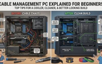
Good PC cable management starts before you tie a single cable: identify every connector, plug the awkward ones in first, and route all cables behind the motherboard tray so airflow and glass panels stay clear. This pc cable management and wiring guide explains what each cable is, which header it belongs to, how to route the thick power cables, and the order that makes the final tidy-up easy instead of painful.
- Quick answer
- The cables inside a typical gaming PC
- Front panel header wiring, explained
- Routing the big power cables
- Fans, fan hubs and RGB
- Front USB, USB-C and audio
- Rear-tray routing and tie-down order
- Modular, semi-modular and non-modular PSUs
- Common mistakes and how to fix them
- Safety and troubleshooting
- How we compared
- Sources
- Frequently Asked Questions
Wiring also carries real consequences. A loose 8-pin CPU plug can stop a PC from starting, a power switch cable on the wrong pins can leave you with a dead case button, and a sharply bent graphics card cable can cause intermittent failures. Neatness is the bonus; correct connections are the point.

VELCRO Brand Reusable Cable Ties, Cord Management, 6in, Black, 100 Pack | Wire And Cable Management Straps For Electronics, Desks, Home Offices, Workstations And Gaming Setups; Adjustable
Included for 'PC Cable Management and Wiring Guide: Headers, Power Cables and Routing Order' because the listing specifies Cord Management and 6in, details this guide uses to compare options.
View on Amazon
VELCRO Brand ONE-WRAP Cable Ties, 8in x 1/2in, Black, 100 Pack | Thin Pre Cut Cable Management Straps For Organizing Cords And Wires In Homes, Offices, Workstations And Data Centers
Included for 'PC Cable Management and Wiring Guide: Headers, Power Cables and Routing Order' because the listing specifies 8in x 1/2in and Black, details this guide uses to compare options.
View on Amazon
VELCRO Brand Reusable Cable Ties, Cord Management, 8in, Black, 150 Pack | Wire Management And Cord Organization Straps; Replace Single Use Zip Ties With Reusable Fasteners For Home And Office
Included for 'PC Cable Management and Wiring Guide: Headers, Power Cables and Routing Order' because the listing specifies Cord Management and 8in, details this guide uses to compare options.
View on AmazonQuick answer
| Order | Do this | Reason |
|---|---|---|
| 1 | Fit the PSU and pass its cables through the rear cut-outs before the motherboard goes in, if the case design allows | Gives you room for your hands |
| 2 | Connect the CPU 4+4 pin (EPS) cable first | It is at the top edge, hidden behind coolers later |
| 3 | Connect the 24-pin ATX cable | It is the stiffest, thickest cable and needs the most routing room |
| 4 | Connect the front panel, USB and audio headers | These small connectors sit at the bottom edge, blocked once the GPU is in |
| 5 | Plug in fans and RGB hubs | Before the GPU, so you can see the headers |
| 6 | Install the graphics card and its power cable last | The heaviest, bulkiest part, and the cable needs a gentle bend |
| 7 | Tie everything down on the rear side | Closing the panel is the real test of the work |
The cables inside a typical gaming PC
Before routing anything, learn what you are holding. Most builders get stuck because several connectors look alike.
| Cable | Connects | How to recognise it | Notes |
|---|---|---|---|
| 24-pin ATX | PSU to motherboard | Widest cable, usually 20+4 pins | Latch clicks on one side |
| EPS 4+4 pin (or 8-pin) | PSU to the CPU power connector | Labelled CPU or EPS; splits into two 4-pin halves | Do not plug a PCIe cable here; the keying differs but some can be forced |
| PCIe 6+2 pin | PSU to graphics card | Labelled PCIe or VGA | Use separate cables for each connector on high-power cards when possible |
| 12V-2×6 (12VHPWR) | PSU or adapter to newer graphics cards | Small 16-pin connector with a side latch | Needs a straight run before any bend |
| SATA power | PSU to SATA drives and some accessories | Flat L-shaped connector, 15 pins | Not used by NVMe M.2 SSDs |
| SATA data | Drive to motherboard | Thin flat cable with L-shaped end | Only for SATA drives |
| Front panel (system) header | Case buttons and LEDs to the motherboard | Tiny individual connectors: power switch, reset, power LED, drive LED | Follow the motherboard manual diagram |
| USB 3.x front header | Case USB-A ports | Wide blue-ish 19 or 20-pin block | Keyed, one way only |
| USB-C front header | Case USB-C port | Small, wide, keyed connector | Only if both the case and motherboard have it |
| HD audio | Case headphone and mic jacks | 9-pin block with one pin missing | Usually labelled HD AUDIO |
| Fan connectors | Case fans, CPU fan, pump | 3-pin or 4-pin small connectors | 4-pin PWM allows speed control |
| Addressable RGB (ARGB) | Fan or strip lighting | 3-pin connector, 5 V | Not interchangeable with 12 V RGB |
| RGB (12 V) | Older style lighting | 4-pin connector | Putting this onto a 5 V ARGB header can damage the lights |
Front panel header wiring, explained
The front panel (system) header is the cluster of tiny connectors that gives your power button, reset button and indicator lights a path to the motherboard. Every board prints a small diagram next to the pins and shows the same diagram in the manual. The labels you will see are:
- PWR_SW or PWRSW: the power button. Two pins, no polarity; either way round works.
- RESET or RST: the reset button. Also two pins, no polarity.
- HDD_LED or HDD+/HDD-: drive activity light. This one has polarity; if it never lights, reverse it.
- PWR_LED or PLED+/PLED-: power light. This also has polarity; plus goes to the labelled plus pin.
- Speaker: some boards have a small buzzer header that gives beep codes. Plug it in if your case supplies one, because it helps troubleshooting.
Switches have no polarity, but lights do. If the lights fail, nothing is damaged. Turn the plug around and try again. Many boards ship with a small adapter block that lets you plug all the fiddly connectors in as one group and then push the block onto the header; use it if yours does, because it is much easier to see the pins when you are working on a bench instead of reaching in blind.
Header pinouts also depend on the board. Because the layout is not identical on every motherboard, trust the manual over memory. The most common error is shifting the whole row one pin left or right, which gives a dead power button. If the case power button does nothing, switch the PSU off at the back, then take the connector off and check that it sits on the correct pair of pins.
Routing the big power cables
The 24-pin ATX cable
This stiff cable runs from the PSU to the right edge of the motherboard. In most mid-tower cases, pass it through the rear cut-out nearest to the connector, run it up behind the motherboard tray, and bring it through the opening next to the connector so that it forms a short, direct path. Bend the cable gently. Do not force a tight right angle at the connector, because that tension can pull on the pins. If the cable looks messy, the problem is usually the wrong cut-out rather than the cable itself.
The EPS CPU cable
The EPS 4+4 pin cable goes to the top-left of the board. Route it behind the tray up through the top rear cut-out and plug it in before installing a tall air cooler or any radiator that covers that area. Lock the plug fully; the latch should click. A missing or half-seated EPS cable is one of the top reasons a first boot shows fans spinning with no display.
Graphics card power cables
Run PCIe cables through the cut-out nearest to the graphics card and keep the bends gentle. For cards with several 8-pin connectors, vendors often recommend separate cables from the PSU instead of one cable with a daisy-chain connector, which spreads the current across more wires. Check your card’s manual and your PSU’s manual for the recommendation specific to your model.
For the newer 12V-2×6 connector, CableMod and darkFlash advise leaving at least 35 mm of straight cable between the plug and any bend and making sure the latch clicks. This is vendor guidance rather than a universal standard, but it is consistent across sources, and it costs nothing to follow. In a narrow case, a native 90 degree cable from the PSU maker can solve a side-panel clearance problem, while a poorly chosen angled adapter can make it worse.
SATA power and drives
If you still use a 2.5 inch SATA drive, mount it on the back of the tray or in the drive bay, and use a single SATA power cable chain that stays tight against the tray. Tidy-looking SATA chains hide well behind a cover plate.
Fans, fan hubs and RGB
A motherboard has only a few fan headers. When you have six or more case fans, a fan hub or a controller built into the case spares you running a separate cable for each one to the board. Typical setups:
| Number of fans | Recommended approach |
|---|---|
| 1 to 4 | Connect straight to motherboard headers; use a splitter cable if needed |
| 5 to 8 | Use a PWM fan hub powered from SATA or Molex, with one lead to a CHA_FAN header for speed control |
| 9+ or daisy-chained RGB fans | Use the manufacturer’s controller or hub, and keep software in one ecosystem |
Check each header’s current rating in the manual. A header designed for one or two fans can be overloaded by a bundle of fans. A powered hub avoids that. Do not mix voltage standards: 5 V ARGB (three-pin) and 12 V RGB (four-pin) look similar and are not interchangeable.
The CPU_FAN header is the one the BIOS watches first. If it reads no speed, some boards refuse to boot or shut down after a few seconds. Plug the cooler fan or the AIO pump here (or into AIO_PUMP if the board has that header), even if a hub controls the case fans.
Front USB, USB-C and audio
The USB 3.x connector is a wide block that only goes in one way. The USB-C front-panel header is smaller and often found near the bottom or edge of the board; it requires a matching cable from the case. The HD audio connector is a nine-pin block with one pin blocked out. All three are best fitted before the graphics card goes in, because they tend to sit at the bottom edge directly under the card.
These connectors are fragile. Always press straight in with even pressure and never bend the board by pushing on one side. If a plug will not seat, check the key and the missing pin rather than increasing the force.
Rear-tray routing and tie-down order
The rear tray gives you only a small amount of space. For reference, Corsair lists about 25 mm of space behind the motherboard tray on the 4000D family, which is typical of mid-tower cases. Some cases give less. That means flat, orderly bundles; cables piled loosely will bulge the rear panel.
- Plan the highway. Decide where the thick cables run. Most cases have routing channels with hook-and-loop straps or tie points near the cut-outs.
- Anchor at the source. Tie the cable near the PSU first, then work toward the motherboard connectors.
- Use the existing tie points. Add straps between tie points rather than in the middle of nowhere.
- Leave slack at the connector. Keep a small service loop so you can unplug without cutting a tie. A tie pulled tight against a connector makes it hard to remove later.
- Group by destination. Keep the 24-pin, EPS and graphics card cables in separate bundles so you can trace each one.
- Check clearance. Close the rear panel gently. If it bulges or resists, rework the bundle instead of forcing it.
- Cut ties last. Use flush cutters or scissors and trim ends so no sharp edges remain.
Hook-and-loop straps are generally better than single-use zip ties for beginners, because you can open them again when you add a drive or change a fan.
Modular, semi-modular and non-modular PSUs
| PSU type | What is detachable | Cable management impact |
|---|---|---|
| Non-modular | Nothing | All cables attached; extra cables must be tucked away |
| Semi-modular | Everything except the 24-pin (and often the CPU cable) | Good balance; unused cables stay in the box |
| Fully modular | Every cable | Easiest to keep tidy; use only the cables you need |
Never reuse a modular cable from another PSU, even from the same brand. The PSU-side pinouts are not standardised across manufacturers or even across models, and a wrong cable can damage components. Use the cables supplied with your exact unit, or cables the manufacturer explicitly states are compatible.
Common mistakes and how to fix them
| Mistake | What happens | Fix |
|---|---|---|
| CPU power cable not connected | Fans spin, no display, no boot | Plug the 4+4 pin EPS cable into the CPU socket header |
| Graphics card power unplugged | No display or warning on screen | Plug in every connector on the card |
| Power switch on wrong pins | Button does nothing | Check the front panel diagram and move the plug |
| Fan hub overloaded or unpowered | Fans do not spin or spin slowly | Provide hub power from the PSU |
| 12 V RGB on 5 V ARGB header | Lights or header damaged | Match the connector to the header voltage |
| Cable pressing on a fan | Noise or blocked blade | Reroute and tie away from blades |
| Sharp bend at a power connector | Strain, poor contact | Add a gentle curve and leave straight run at the plug |
| Cables blocking airflow | Higher temperatures | Move cables out of the intake path |
Safety and troubleshooting
- Switch the PSU off and unplug it before connecting or removing any power cable.
- Touch bare metal on the case to discharge static.
- Do not use excessive force. Connectors are keyed; if they will not fit, they are in the wrong place.
- Do not wrap cables around fans, heatsinks or the back of the GPU.
If the PC does not start after you finish routing, check these in order:
- Reseat the 24-pin and EPS 4+4 pin cables, since these are the ones most likely to be pushed out while you tidy.
- Reseat the RAM, which is easily disturbed if you press on the board while tying cables.
- Confirm all graphics card power connectors and the monitor cable, which must be in the card, not the motherboard.
- Check that the front panel power switch plug is still on its pins.
- Look at the motherboard’s debug LEDs for CPU, DRAM, VGA or BOOT errors.
How we compared
We compared manufacturer manuals, specifications and independent guides named below. We did not build or benchmark these systems ourselves.
Sources
- Motherboard manufacturer installation manuals (ASUS, MSI, Gigabyte, ASRock), front panel and fan header diagrams
- Corsair, 4000D Airflow specification sheet (cable space behind the tray)
- CableMod, 12V-2×6 cable guide
- darkFlash, precautions when using ATX 3.1 power supply GPU cables
- Seasonic, native 12V-2×6 cable guide
- ASRock, 12V-2×6 cable specification page
Frequently Asked Questions
Do I need to plug in every cable that comes with the PSU?
No. Connect only what the build needs: the 24-pin, the CPU EPS cable, graphics card power and any drives. Leave the rest in the box or tucked away. Unused cables in a non-modular unit should be bundled somewhere they cannot touch fans.
Which header does the front panel power button go to?
It goes to the PWR_SW pins in the front panel (system) header, a two-pin pair near the bottom right of the board. The exact pins are in the motherboard manual.
Is it safe to bend the 12V-2×6 cable?
Vendors such as CableMod and darkFlash recommend about 35 mm of straight run from the connector before any bend and a fully seated, clicked-in plug. Follow your PSU and graphics card maker’s instructions when they are stricter.
How many fans can I plug into one motherboard header?
That depends on the header’s current rating, which is listed in the board manual. As a rule, one or two fans is safe for most headers; use a powered fan hub for more.
What is the difference between ARGB and RGB?
Addressable RGB (ARGB) uses a three-pin, 5 V connector and lets each LED be controlled individually. Standard RGB uses a four-pin, 12 V connector and lights the whole strip one colour at a time. They are not interchangeable.
Can I use cables from a different PSU?
Not safely. Pinouts on the PSU end differ between models, and the wrong cable can damage parts. Use the cables supplied with your exact unit or those the maker lists as compatible.
What should I do if the back panel will not close?
Bundle the cables flatter, move thick cables toward the case’s routing channels, and remove unused cables. If the gap is still too small, check the case spec sheet for the maximum space behind the tray.
Does cable management improve temperatures?
Mostly in tight cases, where cables block airflow. In spacious cases the difference is small. The main benefits are easier servicing and avoiding cables touching fans.